IDD
VDDIN Current
VDDIN=3.3V, Controller/Target Ports in idle state
-
6
mA
SW_RON
Analog Switch Path Resistance
DC level around 0.5V
-
10
Ω
CIO
IO pin Capacitance
100Mhz, DC = 0.5V
-
6
pF
CSW
Analog Switch Path total Capacitance, including IO pin capacitance
100Mhz, DC = 0.5V, Master Side Port and Slave Side Port connected by Analog Switch
-
25
pF
Zo_50
Driver Impedance at 50-ohm setting
DC voltage at 0.5*VIO Temperature Range: 0~85°C, nominal VIO
40
60
Ω
Zo_40
Driver Impedance at 40Ω setting
DC voltage 0.5*VIO Temperature Range: 0~85°C, nominal VIO
32
48
Ω
Zo_30
Driver Impedance at 30Ω setting
DC voltage 0.5*VIO Temperature Range: 0~85°C, nominal VIO
24
36
Ω
Zo_20
Driver Impedance at 20Ω setting
DC voltage 0.5*VIO Temperature Range: 0~85°C, nominal VIO
16
24
Ω
Rpu_2k_33
2kΩ Pull-up Resistor value to VDDIN 3.3V
REG#25, SSPzORTS_SDA_Pullup resistor setting = 2kΩ; REG#23, OD_Only bit is set
1.65
2.30
KΩ
Rpu_2k_18
2kΩ Pull-up Resistor value to VIO 1.8V
REG#25, SSPORTS_SDA_Pullup resistor setting = 2kΩ; REG#23, OD_Only bit is cleared
1.65
2.35
KΩ
Rpu_2k_10
2kΩ Pull-up Resistor value to VIO 1.0V
REG#25, SSPORTS_SDA_Pullup resistor setting = 2kΩ; REG#23, OD_Only bit is cleared
1.60
2.20
KΩ
Rpu_1k_33
1kΩ Pull-up Resistor value to VDDIN 3.3V
REG#25, SSPORTS_SDA_Pullup resistor setting = 1kΩ; REG#23, OD_Only bit is set
0.93
1.35
KΩ
Rpu_1k_18
1kΩ Pull-up Resistor value to VIO 1.8V
REG#25, SSPORTS_SDA_Pullup resistor setting = 1kΩ; REG#23, OD_Only bit is cleared
0.88
1.35
KΩ
Rpu_1k_10
1kΩ Pull-up Resistor value to VIO 1.0V
REG#25, SSPORTS_SDA_Pullup resistor setting = 1kΩ; REG#23, OD_Only bit is cleared
0.84
1.20
KΩ
Rpu_500_33
500Ω Pull-up Resistor value to VDDIN 3.3V
REG#25, SSPORTS_SDA_Pullup resistor setting = 500Ω; REG#23, OD_Only bit is set
0.45
0.66
KΩ
Rpu_500_18
500Ω Pull-up Resistor value to VIO 1.8V
REG#25, SSPORTS_SDA_Pullup resistor setting = 500Ω; REG#23, OD_Only bit is cleared
0.44
0.66
KΩ
Rpu_500_10
500Ω Pull-up Resistor value to VIO 1.0V
REG#25, SSPORTS_SDA_Pullup resistor setting = 500Ω; REG#23, OD_Only bit is cleared
0.41
0.58
KΩ
Rpu_250_33
250Ω Pull-up Resistor value to VDDIN 3.3V
REG#25, SSPORTS_SDA_Pullup resistor setting = 250Ω; REG#23, OD_Only bit is set
0.23
0.33
KΩ
Rpu_250_18
250Ω Pull-up Resistor value to VIO 1.8V
REG#25, SSPORTS_SDA_Pullup resistor setting = 250Ω; REG#23, OD_Only bit is cleared
0.22
0.33
KΩ
Rpu_250_10
250Ω Pull-up Resistor value to VIO 1.0V
REG#25, SSPORTS_SDA_Pullup resistor setting = 250Ω; REG#23, OD_Only bit is cleared
0.22
0.33
KΩ
VILM_OD
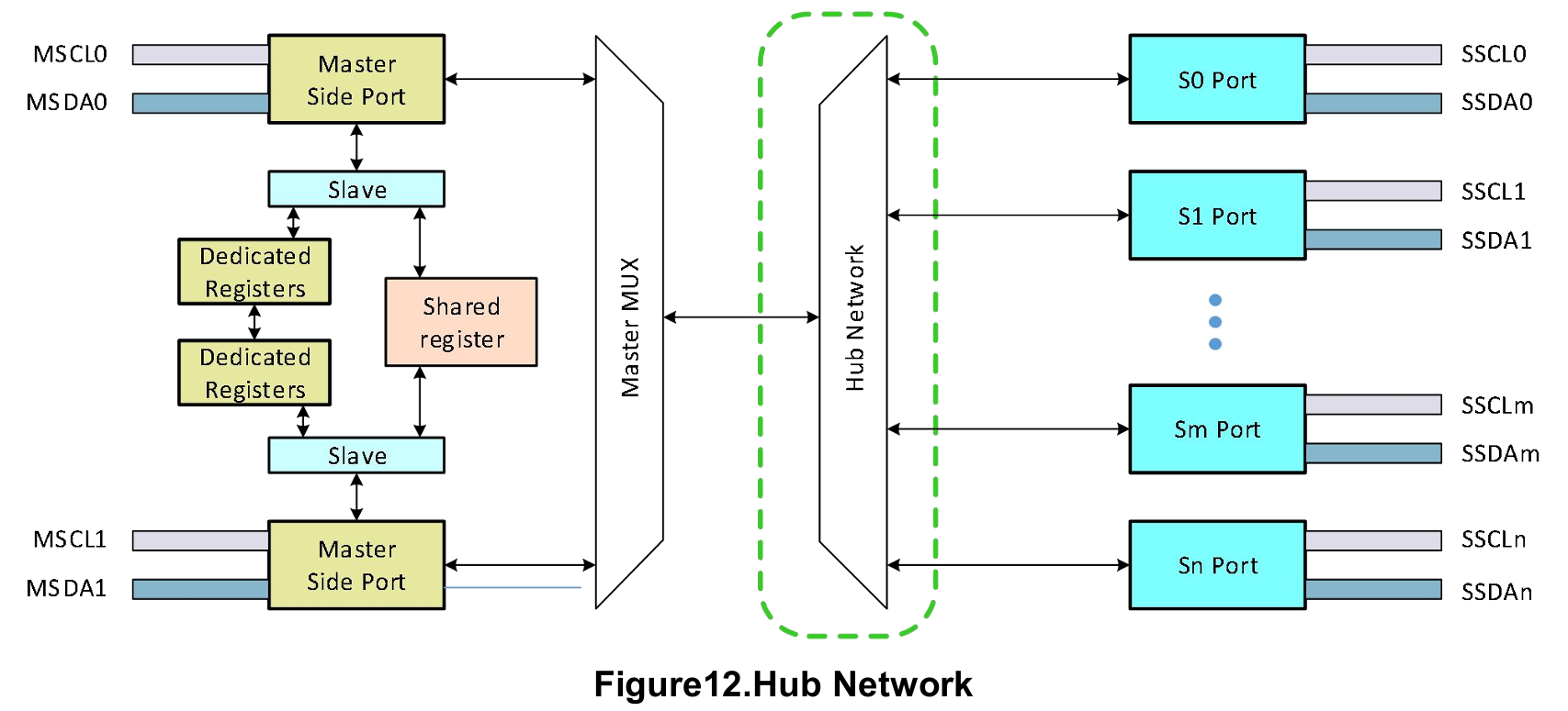
Input low voltage Master Side Ports in OD_Only Mode
DC swipe, OD Only Operation
-0.3
0.5
V
VIHM_OD
Input high voltage Master Side Ports in OD_Only Mode
DC swipe, OD Only Operation
0.7
3.6
V
VILM
Input low voltage Master Side Ports in OD/PP compatible Mode
DC swipe
-0.3
0.35VIO
V
VIHM
Input high voltage Master Side Ports in OD/PP compatible Mode
DC swipe
0.65*VIO
VIO+0.3
V
VILS_OD
Input low voltage Slave Side Ports in OD_Only Mode
DC swipe, OD Only Operation
-0.3
0.6
V
VIHS_OD
Input high voltage Slave Side Ports in OD_Only Mode
DC swipe, OD Only Operation
0.85
VDDIIN+0. 3
V
VILS
Input low voltage Slave Side Ports in OD/PP compatible Mode
DC swipe, Push/Pull Operation, GPIO, Bus Agent Mode
-0.3
0.35*VIOS
V
VIHS
Input high voltage Slave Side Ports in OD/PP compatible Mode
DC swipe, Push/Pull Operation, GPIO, Bus Agent Mode
0.65*VIOS
VIOS+0.3
V
RDRV_EXT
Slave Side Port external slave device’s pull down driver impedance
Measure at VILS Level.
-
100
Ω
CLOAD
Slave Side Port maximum Capacitive Load
Lumped capacitance, including the capacitance of the PCB trace and device pin capacitance
-
200
pF
VIL_MSEL
Input low voltage of MSEL pin
DC swipe
-0.3
0.3
V
VIH_MSEL
Input high voltage of MSEL pin
DC swipe
0.75
3.6
V
ILMSEL[5]
MSEL leakage current tolerance
Leakage current limit of keeping the MSEL as HiZ state
-
3
uA
RDRV_MSEL
MSEL Pin driver resistance for static logic setting[6]
The resistance of IO driver (or tie high/tie-low resistor) drives MSEL pin to static logic high or logic low.
-
1
KΩ
VOL_ODL
Output low voltage I2C/I3C Ports
DC swipe, with 1K internal pull-up, VIO<1.5V
-
0.25
V
VOL_ODH
Output low voltage I2C/I3C Ports
DC swipe, with 1K internal pull-up, VIO>=1.5V
-
0.35
V
VOL_PP
Output low voltage I2C/I3C Ports
DC swipe, IIoad = 4mA
-
Zo*IIoad* 1.25
V
VOH_PP
Output high voltage I2C/I3C Ports
DC swipe, 4mA load, VIO=1.0V, 1.1V, 1.2V, 1.8V; Zo calibrated
VIO - Zo*Iload* 1.3
-
V
VIO_PG_Clr_Lo_10[9]
VIO Power Good Status Clear Low Threshold for 1.0V setting
DC swipe, check Power Good Status Register
0.85
0.9
V
VIO_PG_Clr_Hi_10[10]
VIO Power Good Stats Clear High Threshold for 1.0V setting
DC swipe, check Power Good Status Register
1.1
1.17
V
VIO_PG_Clr_Lo_11
VIO Power Good Status Clear Low Threshold for 1.1V setting
DC swipe, check Power Good Status Register
0.92
0.99
V
VIO_PG_Clr_Hi_11
VIO Power Good Status Clear High Threshold for 1.1V setting
DC swipe, check Power Good Status Register
1.21
1.29
V
VIO_PG_Clr_Lo_12
VIO Power Good Status Clear Low Threshold for 1.2V setting
DC swipe, check Power Good Status Register
1.01
1.08
V
VIO_PG_Clr_Hi_12
VIO Power Good Status Clear High Threshold for 1.2V setting
DC swipe, check Power Good Status Register
1.32
1.39
V
VIO_PG_Clr_Lo_18
VIO Power Good Status Clear Low Threshold for 1.8V setting
DC swipe, check Power Good Status Register
1.51
1.62
V
VIO_PG_Clr_Hi_18
VIO Power Good Status Clear High Threshold for 1.8V setting
DC swipe, check Power Good Status Register
1.98
2.09
V
HYS_PG_10[11]
VIO Power Good Set/Clear Threshold Hysteresis for 1.0V VIO
DC swipe, check Power Good Status Register
0.033
0.035
V
HYS_PG_11
VIO Power Good Set/Clear Threshold Hysteresis for 1.1V VIO
DC swipe, check Power Good Status Register
0.033
0.035
V
HYS_PG_12
VIO Power Good Set/Clear Threshold Hysteresis for 1.2V VIO
DC swipe, check Power Good Status Register
0.033
0.035
V
HYS_PG_18
VIO Power Good Set/Clear Threshold Hysteresis for 1.8V VIO
DC swipe, check Power Good Status Register
0.048
0.052
V
VIO_PG_Set_Lo
VIO(1.0/1.1/1.2/1.8V) Power Good Status Set Low Threshold
DC swipe, check Power Good Status Register
-
VIO_PG_Clr_Lo_10/11/12/18 + HYS_PG_10/11/12/18
V
VIO_PG_Set_Hi
VIO(1.0/1.1/1.2/1.8V) Power Good Status Set High Threshold
DC swipe, check Power Good Status Register
-
VIO_PG_Clr_Lo_10/11/12/18 + HYS_PG_10/11/12/18
V